WinCal Support
Access answers to frequently asked questions, demo requests, and opportunity to provide feedback
General RF Calibration FAQ
This question may indicate a basic misunderstanding of on-wafer calibration. Let's try to correct it.
In coaxial calibrations the standards are unique devices and since they have a unique connector can have only a single electrical characteristic. In on-wafer probing the electrical behavior of the standards are dependent upon the probe and how it is placed.
The shape and configuration of the standard will also be important. FormFactor makes a variety of impedance standard substrates (ISS's). There are versions for probes with standard or wide pitch with choices for ground-signal or ground-signal-ground tip configurations. In addition there are general purpose, specialty, and custom configurations supporting a wide variety of applications.
The calibration coefficients are supplied with the probe, not with the impedance standard substrate. Calibration coefficients may be found on the data sheet that shipped with your probe. The calibration coefficients for your probe / ISS combination may also be found using WinCal (Tools -> View Probes and Matching ISS/CSR). For 250 um pitch probes either the standard pitch or the wide-pitch ISS may be used. The calibration coefficients that are normally supplied correspond to the standard pitch ISS. The values will be somewhat different when using the wide pitch ISS.
The only calibration term not supplied with the probe is the Thru standard delay. For standard pitch probes with proper alignment of probe separation using the alignment marks provided on the ISS, the Thru delay will be 1 ps. For wide-pitch ISS's the Thru delay is 4 ps.
Your Cal information consists of three numbers for each probe and a number for the Thru standard. Each Probe: #1 Co Open circuit capacitance, #2 Ls Short circuit inductance, #3 Lterm load inductance. Thru: #1 Delay In most cases the load standards are 50 ohms. Where the 500 ohms that you see in the calkit comes from is in the implementation of the load inductance. The HP 8510 does not directly support entry of load inductance. Instead we use the offset load capability. By choosing a very high impedance (500 ohms) for the offset and the corresponding delay (L/500) we get behavior equivalent to the inductance that we want. This method can also be used for the short circuit inductance.
In all cases the three terms for the probes are supplied with the probe. Enter them as described above. The Thru delay is not all that well documented. Use 1 ps for probes with 250 um pitch or less. Larger pitch probes use Thru delay of 4 ps.
If TRL calibration is used the delay of the long lines will need to be supplied to WinCal or directly to the VNA. These delays are readily determined from the drawing supplied with the ISS. Simply measure the line using a scale provided on the ISS for this purpose. Remember to allow for the probe contact overlap - about 50 um on each end. Each 130 um (0.130 mm) of length corresponds to approximately 1 ps, so delay may be calculated from T (ps) = Length (mm)/0.13 (best fit).
The 101-190 TRL line lengths as measured after LRRM calibration:
150 um 1 ps
450 um 3.2 ps
900 um 6.6 ps
1800 um 13.5 ps
3500 um 26.6 ps
5250 um 40.4 ps
The 106-682 wide pitch GSG ISS has 4 ps Thru's and lines of 25, 50, and 50 ps. The straight CPW's on the 106-686 GP membrane ISS are 3.8, 5.8, 11.5, 17.1, 22.8, 28.3, 34.2, 39.7, 45.3, 52.7, 60.4, and 67.7 ps.
Here are the delays for the lines in the upper right corner of the 005-016 ISS. They are in order from left to right, then top to bottom. "st" indicates a straight line, "ra" indicates a right angle line.
st 19.3 ps st 8 ps
st 19.3 ps st 2.7 ps st 4.7 ps
st 17 ps st 10.8 ps
st 24.2 ps ra ~5 ps
st 24.2 ps ra ~15 ps
st 41.1 ps
Treat these numbers as estimates - not as precise. The ra numbers are even less precise. The SOLR calibration requires only an estimate of the delay of the line which is used to determine the particular sign of a square root.
After completing the SOLR calibration, look at a polar plot of S21 for the R (reciprocal Thru) standard that was used in the cal. The phase response should be roughly continuous with frequency (for closely spaced measurement frequencies). If there is a step change in phase then the estimate of the Thru delay entry may need to be adjusted and the calibration recomputed.
Once a proper SOLR solution is completed the measurement of the delay of the Thru with the calibration turned on will be accurate and can be used for further work. Note that the best measurement of delay using a VNA is obtained by displaying the transmission phase and adjusting the "electrical delay" for constant zero phase over the measurement bandwidth. The 'delay' display format uses a calculation of the difference in phase between successive frequency points and can be very noisy for closely spaced frequencies.
This kind of step behavior in the transmission phase indicates that the SOLR algorithm has not found the proper root choice in solving for the standard. Adjust your guess for the Thru delay estimate to eliminate the phase step behavior.
WinCal FAQ
Launch WinCal, and choose Licensing from the Help menu for license activation and deactivation information.
This issue is resolved in WinCalXE 4.7.2. A free upgrade is available to download from the FlexNet License Portal for users of 4.7.
The Flexera portal has increased their security measures and the network protocol TLS 2.1 is now required for activation and deactivation of WinCal licenses. It is available in Windows 7 and later, but WinCal XE 4.7.0 and 4.7.1 do not make use of it. The 4.7.2 update is now available for download on the FormFactor pages of the FlexNet portal (free to 4.7 .x users). This new version will enable the required protocol and is available to download from the portal under the “Release Archive” tab in the Download Center.
Windows XP cannot do online activation/deactivation at all. It does not support TLS 1.2, so only offline activation/deactivation is available there.
WinCal 4.8.x does not need any updates for this new portal requirement.
If multiple users log on to the computer where WinCal is installed you may get the following errors in the EventWindow:
QueryLicenseInfo failed: A service system error was encountered: Failed file open. [1,7DF,9,0[73000041,5,400703F3]]
WinCal license is invalid: AcquireLicensesFromTrustedStorage failed: A service system error was encountered: Failed file open. [1,7DF,9,0[73000041,5,400703F3]]
If you have more than one user on the same PC, those other users can use WinCal without having to separately activate the license. Only the first user that installs it need to do that. However, all Windows user logins need to have read access to the folder that holds the files we call “Trusted Storage”. It is a folder under Program Data and on Windows 7 it is “C:\ProgramData\Cascade Microtech\WinCal XE 4.7\FlexNetStorage”. If you get the errors above in WinCal’s Event Window, you have access right problems.
This issue is resolved in WinCalXE 4.8 and later by using a folder under "C:\Users\Public\Documents" instead.
WinCal 3.x and 2006 are no longer supported. They have been replaced by WinCal. Contact Sales for instructions how to get WinCal.
Advanced calibrations (with switching terms) are stored as 16-terms calibrations. Each error set consists of a few files that are stored together in one folder.
They are of course converted to 12-term before being sent to a VNA. WinCal can also convert them to 12-term on command and save them as S1P files with one error coefficient per file in a new folder.
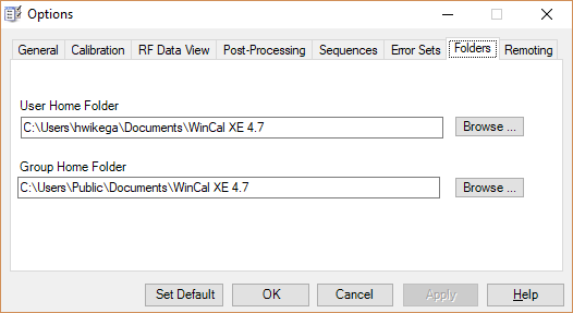
Error sets are store in a subfolder called ErrSets under the folder you have designated as “User Home Folder” in Options. (Showing default for user name hwikega on Windows 7)
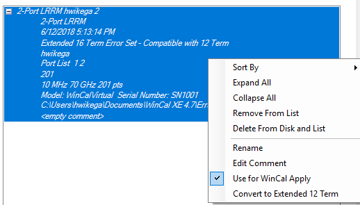
To handle Error Sets, use the menu “Tools | Error Set Manager” in the main program. In the Error Set Manager all saved Error Sets are showing, and WinCal saves each one you
make. (It may also be a good idea to clean out old ones once in a while.)
Find the 16-term Error Set you want to save as 12-term and right click on it. You will see a pop-up menu, where the last menu option is Convert to Extended 12 Term
Note: WinCal XE always saves SOL and SOLT in the 12 term format directly, since they do not have switching terms (not considered advanced calibrations).
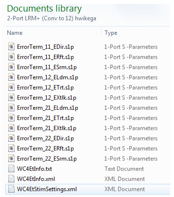
Make this conversation and WinCal makes a new folder with the 12 term content. It will have these kinds of files, where each 12-term error coefficient is in a separate S1P file.
The data can be reached via RF Data Viewer:
When data is measured in Calibration form, the “View” button becomes available.
After you click on the “View” button, the data will be downloaded into a Report
In the Report Tab, you can now see measurement results on a graph
You can also view your measurement results by clicking View > Data Items
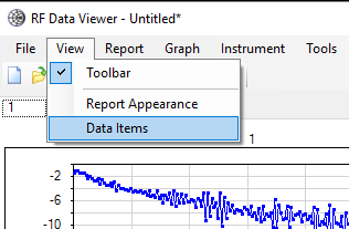
If you right click on the data item, a pop-up menu will appear with several options to choose from.
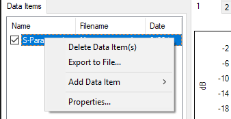
To see the numerical data, select “Properties” on the pop-up menu, this will appear as an SnP file providing the details of your measurement
An old version of WinCal XE had this limitation. It has since been fixed. Please upgrade to the current version.
The “WinCal XE Data Post Processing Tutorial” provides instruction on using WinCal XE post processing capability. Make sure the main form shows at full size (rightmost toolbar button). Select the Tutorial tab, then press “Other” and the selection of this tutorial will be available.
Yes, there are several examples. In the main form, use the menu “Help-Copy Examples to My Documents“. This will copy all example files from the distribution to the “User Home Folder”, typically “My Documents\WinCal XE 4.7\Examples” belonging to the currently logged in user. The “User Home Folder” can be changed in Options-Folders tab. Once the examples are there you can open, copy and modify them to your own needs. If you modify them, we recommend that you copy them to a new subfolder to your “User Home Folder” first, so that a new “Help-Copy Examples to My Documents” won’t overwrite your customized version.
WinCal comes with powerful validation tools. For an overview of these tools go to the main form and use the menu “Help-Documentation Folders“. It will open the Windows Explorer to this folder. Select the subfolder “Application Toolkits” and open the file “Calibration Validation and System Comparison Tools.pdf”
WinCal comes with many tools to assist you with your device characterization tasks. In the main form, use the menu “Help-Documentation Folders“. It will open the Windows Explorer to this folder. Select the subfolder “Application Toolkits” and open the file “Device Characterization Tools.pdf”which describes many of the tools.
Yes. In the main form, use the menu “Wizards-Wizard Script Editor”. A better way may be to start with an existing Wizard and modify it. Select the Wizard tab in the main form. Press “More Wizards” and right click on the Wizard you want to base your custom Wizard on. Right click and select “Create Copy for User” or “Create Copy for Group” depending on if you want to share it or not. The original Wizard gets copied there and you can then right click on this new copy and select “Edit”. After editing you can save it with a new name, but it will not replace the original Wizard even if not renamed. They reside in different folders.
This is an indication of poor repeatability in your measurement system. One way this can occur is when your calkit was radically misdefined or perhaps you measured a short circuit when you should have measured an open. This can create a high sensitivity to measurement system variability.
More likely is that something is wrong in the measurement system. Using your VNA with calibration turned off, compare the magnitude of measured reflection coefficient for a load and a short on each port. Expect more than 10 dB of change in order to get good calibration results.
This experiment can be repeated with coaxial standards at the ends of the cable, and at the VNA front panel to further isolate the problem. If the problem occurs when using the VNA alone there may be a problem with the VNA. Check your VNA setup. Low source power, high port attenuation, or ramp sweep will reduce VNA repeatability. Using inadequate averaging can also reduce dynamic range.
Check all cables and connections. Properly torque all connectors. Make sure that you are using good quality phase stable cables. With a poor cable any strain or inadvertent bump from the user will change the electrical behavior enough to spoil a calibration. Semi-rigid cables may be used but avoid any stresses at the connectors and properly secure the cable to minimize vibration or other motion.
If your system is performing at its best the thresholds for ‘good’ and ‘acceptable’ calibrations can be changed to provide guidance for nominal system performance.
This kind of step behavior in the transmission phase indicates that the SOLR algorithm has not found the proper root choice in solving for the standard. Adjust your guess for the Thru delay estimate to eliminate the phase step behavior.
For WinCalXE 4.6 and earlier
For a “Demo & Virtual” installation, where no key is needed, it is actually normal operation. Note that for a full 30-day Demo with a key you will need to choose default or full installation and then have the key attached. To only have the Virtual VNA available is a symptom of the hardware key (USB or parallel) either being the wrong one or not attached at all. It could also be a system problem, perhaps with the install of the driver for the key.
For WinCalXE 4.7 and later
Verify you have a valid license in WinCalXE (Help -> Licensing)
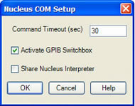
The first thing to check is the obvious physical connections. GPIB contacts can slip out if not screwed in properly. Another common cause is that Nucleus is configured to be talker/listener and is conflicting with WinCal’s need to be Controller. Either use a GPIB switch box (and configure WinCal to use it, see below), or configure Nucleus to not be controlled over GPIB at all (Nucleus Hardware Setup – see Nucleus manual). You can try to select the Switchbox in WinCal even if you don’t have one. It should still stop Nucleus from using GPIB when WinCal needs it.
An early version had a file syntax flaw regarding the line breaks for a 3-port data set. This has since been fixed. Please upgrade to the current version.
Yes, the Calibration tab in Options has a checkbox for that.
- This issue is resolved in WinCalXE 4.7.1. A free upgrade is available to download from the FlexNet License Portal for users of 4.7.
Background
In Velox 2.2 the MessageServer was rewritten in C#.Net and the newer DLL interface (Vx.MessageServe.dll) should be used. WinCal 4.7 installs the older version of this DLL to its SysBin folder. WinCal 4.6 did not install this DLL and will connect ok, since it gets the DLL from Velox path. This DLL is no longer installed in versions 4.7.1 and later.
Workarounds
- Use Sockets Instead. The Socket connection still works, so change to using Velox, LAN (Sockets) and put in localhost for IP address.
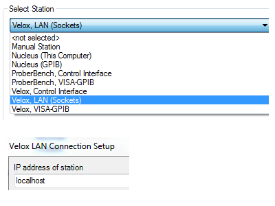
- Remove The DLL from WinCal’s install folder. The (typical) install folder for WinCal on Windows 7 is: C:\Program Files (x86)\Cascade Microtech\WinCal XE 4.7\SysBin
- Make sure WinCal is closed
- Navigate to the folder above, then remove Vx.MessageServe.dll
- Reboot and it should not work, since WinCal would pick up the newer Velox 2.2 DLL from the system path.
- Use Sockets Instead. The Socket connection still works, so change to using Velox, LAN (Sockets) and put in localhost for IP address.