Today’s mainstream devices such as automotive applications are having to operate in a wider operating temperature range, a regime which in the past was more limited to military applications. It becomes increasingly critical to characterize device behavior and durability over an ever-wider range of temperatures. Customers are commonly testing in the range of -40˚C to 125˚C. Often wafer testing may involve a complete set of parametric tests at each of four temperature steps within this range. Some cases call for even wider ranges, such as -55˚C to 200˚C, and wafer reliability testing may call for temperatures as high as 300˚C.
This ongoing expansion in the number of required temperature steps during wafer-level testing can quickly consume a significant share of valuable lab time. The issue is compounded by the demand for increasingly large amounts of data to be extracted at each temperature step. A complete set of test cycles at all required temperature points might now take up to 72 hours, or more.
As a result, it becomes imperative to automate transitions between setpoint temperatures, automate wafer realignment at each temperature, and automate probe-to-pad realignment at each die. Any approach to automating the test cycle must account for the thermal drift introduced during the wafer soak and die soak phases. Both alter the geometry between the chuck, which holds the wafer, the platen which is the surface the probe positioners mount on and crucially the positioner mechanics themselves.
In either case, heat-induced expansion changes the position of the probes on the wafer surface. During wafer soak, the chuck first reaches the required temperature, which in turn heats the platen until equilibrium is reached between the two. In addition, the station mechanics also need time to expand. The time required to reach this equilibrium is called the wafer soak time.
Any approach to automating and minimizing the test cycle at each temperature point must address three major issues:
1. It must automate the manual realignment process required to compensate for thermal drift.
2. It should eliminate the idle time by managing the transition times and soak times with maximum efficiency by automatically realigning probes to pads after a thermal transition, or after a die step move is complete including soaking. This process includes using longer soaks when test time on a particular device is small or lengthening when test times are longer
3. The system architecture should readily accommodate various components that minimize the impact of thermal drift at high temperatures.
We have integrated a number of our proprietary technologies to produce Contact Intelligence, which enable automation and compress cycle times to an absolute minimum. Contact Intelligence automation targets the realignment process required to synchronize the probe tips with the target pads on the wafer surface. In many instances, manual probe adjustments can be time-consuming, especially in cases where they are needed not only after a temperature transition, but also after stepping to a new probe location. This is especially true when the transitions involve widely separated probe points on the wafer surface, which amplifies the “hot spot” effect.
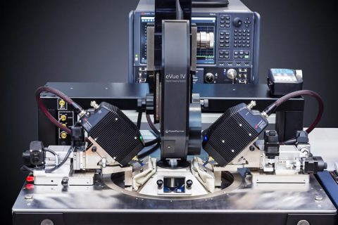
Contact Intelligence is incorporated into the CM300xi and SUMMIT200 probe systems, which sense, learn and react to alignment issues over multiple temperatures and small pad layouts. Contact Intelligence automatically adapts and adjusts to provide the most accurate probe-to-pad alignment for a broad array of wafers, materials and devices. It applies an unprecedented level of machine intelligence to the acceleration of test cycles, while providing the highest levels of accuracy, reliability and stability in increasingly complex test environments.
